
This article is about interfacing a hex key pad to 8051 microcontroller. A clear knowledge on interfacing hex key pad to 8051 is very essential while designing embedded system projects which requires character or numeric input or both. For example projects like digital code lock, numeric calculator etc. Before going to the interfacing in detail, let’s have a look at the hex keypad.
Hex keypad.
Hex key pad is essentially a collection of 16 keys arranged in the form of a 4×4 matrix. Hex key pad usually have keys representing numerics 0 to 9 and characters A to F. The simplified diagram of a typical hex key pad is shown in the figure below.
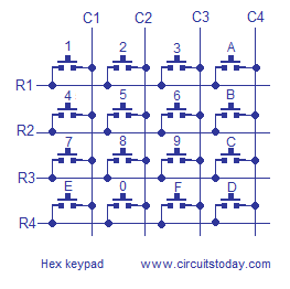
The hex keypad has 8 communication lines namely R1, R2, R3, R4, C1, C2, C3 and C4. R1 to R4 represents the four rows and C1 to C4 represents the four columns. When a particular key is pressed the corresponding row and column to which the terminals of the key are connected gets shorted. For example if key 1 is pressed row R1 and column C1 gets shorted and so on. The program identifies which key is pressed by a method known as column scanning. In this method a particular row is kept low (other rows are kept high) and the columns are checked for low. If a particular column is found low then that means that the key connected between that column and the corresponding row (the row that is kept low) is been pressed. For example if row R1 is initially kept low and column C1 is found low during scanning, that means key 1 is pressed.
Interfacing hex keypad to 8051.
The circuit diagram for demonstrating interfacing hex keypad to 8051 is shown below.Like previous 8051 projects, AT89S51 is the microcontroller used here. The circuit will display the character/numeric pressed on a seven segment LED display. The circuit is very simple and it uses only two ports of the microcontroller, one for the hex keypad and the other for the seven segment LED display.

Interfacing hex keypad to 8051
The hex keypad is interfaced to port 1 and seven segment LED display is interfaced to port 0 of the microcontroller. Resistors R1 to R8 limits the current through the corresponding segments of the LED display. Capacitors C1, C2 and crystal X1 completes the clock circuitry for the microcontroller. Capacitor C3, resistor R9 and push button switch S1 forms a debouncing reset mechanism.
Program.
ORG 00H
MOV DPTR,#LUT // moves starting address of LUT to DPTR
MOV A,#11111111B // loads A with all 1's
MOV P0,#00000000B // initializes P0 as output port

BACK:MOV P1,#11111111B // loads P1 with all 1's
     CLR P1.0  // makes row 1 low
     JB P1.4,NEXT1  // checks whether column 1 is low and jumps to NEXT1 if not low
     MOV A,#0D   // loads a with 0D if column is low (that means key 1 is pressed)
     ACALL DISPLAY  // calls DISPLAY subroutine
NEXT1:JB P1.5,NEXT2 // checks whether column 2 is low and so on...
      MOV A,#1D
      ACALL DISPLAY
NEXT2:JB P1.6,NEXT3
      MOV A,#2D
      ACALL DISPLAY
NEXT3:JB P1.7,NEXT4
      MOV A,#3D
      ACALL DISPLAY
NEXT4:SETB P1.0
      CLR P1.1
      JB P1.4,NEXT5
      MOV A,#4D
      ACALL DISPLAY
NEXT5:JB P1.5,NEXT6
      MOV A,#5D
      ACALL DISPLAY
NEXT6:JB P1.6,NEXT7
      MOV A,#6D
      ACALL DISPLAY
NEXT7:JB P1.7,NEXT8
      MOV A,#7D
      ACALL DISPLAY
NEXT8:SETB P1.1
      CLR P1.2
      JB P1.4,NEXT9
      MOV A,#8D
      ACALL DISPLAY
NEXT9:JB P1.5,NEXT10
      MOV A,#9D
      ACALL DISPLAY
NEXT10:JB P1.6,NEXT11
       MOV A,#10D
       ACALL DISPLAY
NEXT11:JB P1.7,NEXT12
       MOV A,#11D
       ACALL DISPLAY
NEXT12:SETB P1.2
       CLR P1.3
       JB P1.4,NEXT13
       MOV A,#12D
       ACALL DISPLAY
NEXT13:JB P1.5,NEXT14
       MOV A,#13D
       ACALL DISPLAY
NEXT14:JB P1.6,NEXT15
       MOV A,#14D
       ACALL DISPLAY
NEXT15:JB P1.7,BACK
       MOV A,#15D
       ACALL DISPLAY
       LJMP BACK

DISPLAY:MOVC A,@A+DPTR // gets digit drive pattern for the current key from LUT
        MOV P0,A       // puts corresponding digit drive pattern into P0
        RET

LUT: DB 01100000B // Look up table starts here
     DB 11011010B
     DB 11110010B
     DB 11101110B
     DB 01100110B
     DB 10110110B
     DB 10111110B
     DB 00111110B
     DB 11100000B
     DB 11111110B
     DB 11110110B
     DB 10011100B
     DB 10011110B
     DB 11111100B
     DB 10001110B
     DB 01111010B
     END
About the program.
Firstly the program initializes port 0 as an output port by writing all 0′s to it and port 1 as an input port by writing all 1′s to it. Then the program makes row 1 low by clearing P1.0 and scans the columns one by one for low using JB instruction.If column C1 is found low, that means 1 is pressed and accumulator is loaded by zero and DISPLAY subroutine is called. The display subroutine adds the content in A with the starting address of LUT stored in DPTR and loads A with the data to which the resultant address points (using instruction MOVC A,@A+DPTR). The present data in A will be the digit drive pattern for the current key press and this pattern is put to Port 0 for display. This way the program scans for each key one by one and puts it on the display if it is found to be pressed.
Notes.
- The 5V DC power supply must be well regulated and filtered.
- Column scanning is not the only method to identify the key press. You can use row scanning also. In row scanning a particular column is kept low (other columns are kept high) and the rows are tested for low using a suitable branching instruction. If a particular row is observed low then that means that the key connected between that row and the corresponding column (the column that is kept low) is been pressed. For example if column C1 is initially kept low and row R1 is observed low during scanning, that means key 1 is pressed.
- A membrane type hex keypad was used during the testing. Push button switch type and dome switch type will also work. I haven’t checked other types.
- The display used was a common cathode seven segment LED display with type number ELK5613A. This is just for information and any general purpose common cathode 7 segment LED display will work here.
No comments:
Post a Comment